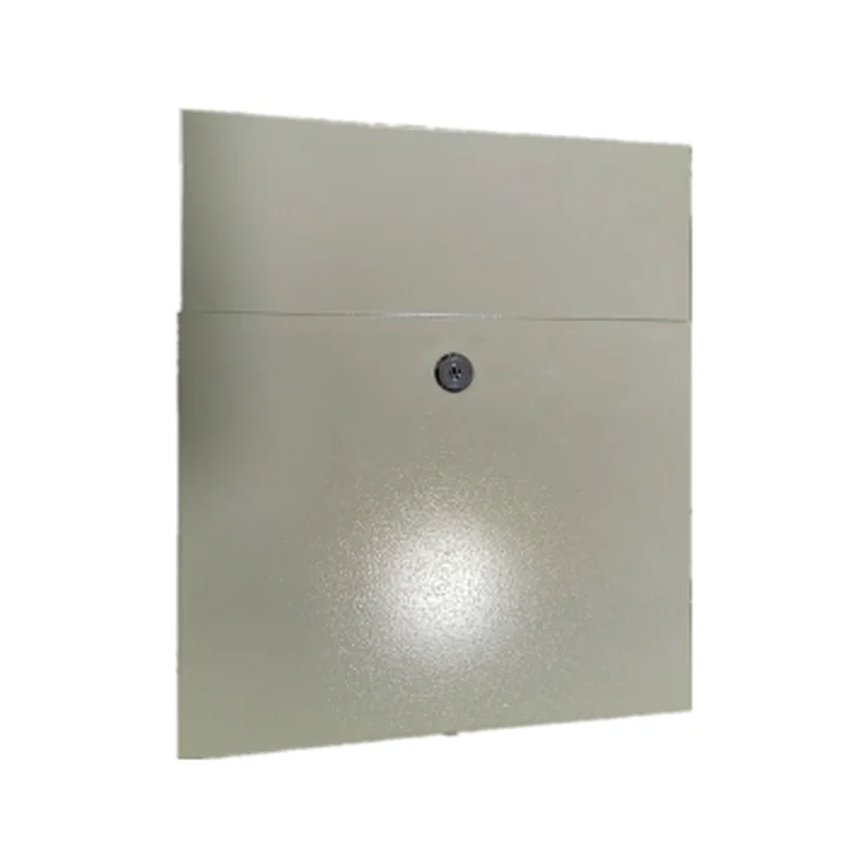
An ODF (optical distribution frame) is the panel or cabinet where incoming fibre cables are terminated on adapters, spliced to pigtails, patched to the equipment they serve and stored with slack inside bend-radius limits. It does the job of a fibre patch panel and a splice enclosure in one. A rack-mount ODF such as the ARC-ODF-RM-2U (2U, 19-inch, 24 cores on two sliding trays) belongs in the comms-room rack next to the OLT or core switch. A wall-mount ODF such as the ARC-ODF-WM-24 (a lockable two-door steel fibre termination box for 24 SC, 24 FC or 48 LC-duplex) belongs at the building entry or in a riser.
Quick pick: head-end, ISP point of presence or data-centre rack: rack-mount. Building entry, MDU riser, plant room or any site with no rack: wall-mount. Exposed outdoor positions need an IP-rated terminal or closure instead.
Planning a fibre build? Call ARC IP Networks on 1300 100 440 or send us your core count and site details for an ODF and patching bill of materials with project pricing.
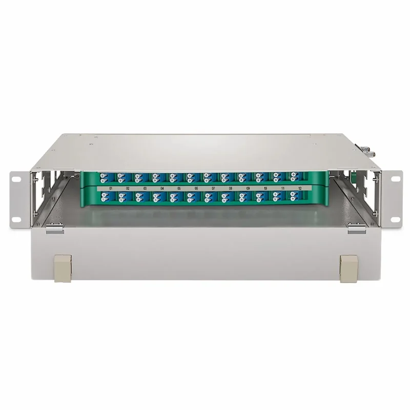
What does ODF mean?
ODF stands for optical distribution frame. It is the organised meeting point between the fibre cables coming into a building or rack and the equipment or drops they serve. A good ODF does four jobs:
- Terminate. Every fibre ends on an adapter port with a fixed, labelled position.
- Splice. Splice trays hold the fusion joints between the incoming cable and factory-made pigtails.
- Patch. Patch cords run from the front of the adapters to the OLT, switch, router or onward cable.
- Protect and store. Slack is coiled inside bend-radius limits, so fibres aren't kinked or crushed.
That turns a wall or rack of loose fibre into infrastructure that can be audited, re-patched and grown.
ODF, fibre patch panel or fibre termination box?
You'll see all three terms on drawings and quotes. They overlap:
| Term | What people usually mean | ARC DATA example |
|---|---|---|
| ODF (optical distribution frame) | Terminate, splice, patch and store slack in one frame or cabinet | ARC-ODF-RM-2U, ARC-ODF-WM-24 |
| Fibre patch panel | The adapter panel that patch cords plug into; often a rack panel. An ODF does this job and also houses the splices | ARC-ODF-RM-2U |
| Fibre termination box | A wall box where a cable is terminated and spliced, often at a building entry | ARC-ODF-WM-24 |
Usage varies between suppliers and drawings. Check what each line on a quote actually includes.
Rack-mount vs wall-mount ODF: the comparison
Both ARC DATA ODFs terminate, splice and patch up to 24 fibres. The difference is where they go and how they're built. Figures below are from the ARC DATA datasheets.
Swipe the table sideways to compare both ODFs →
| ARC-ODF-RM-2U (rack-mount) | ARC-ODF-WM-24 (wall-mount) | |
|---|---|---|
| Mounting | 19-inch rack, 2U | Wall, two-door cabinet |
| Capacity | 24 cores: 2 sliding trays x 12 SC | Up to 24 SC, 24 FC or 48 LC-duplex |
| Adapters | Universal trays for SC, LC or FC; type specified at order | SC, LC-duplex or FC on screwless six-position holders; type specified at order |
| Access | Each tray slides forward on its own; the other stays in service | Central adapter board separates incoming feeder from outgoing drops |
| Splicing | Integrated splice trays with slack and bend-radius management | Integrated splice tray with slack and bend-radius control |
| Cable entry | Top or bottom, free allocation; ribbon and bunch cable, adjustable hangers | Top and bottom |
| Size | 482 x 270 mm (W x D), 2U high | 420 x 425 x 100 mm (W x H x D) |
| Insertion loss | 0.3 dB or less | Not stated on the datasheet |
| Return loss | PC 45 dB, UPC 50 dB, APC 60 dB or better | Not stated on the datasheet |
| Operating temperature | -40 °C to +60 °C | -30 °C to +75 °C |
| Humidity | 95% or less at +40 °C | 90% or less at +30 °C |
| Placement | Indoor rack | Indoor or sheltered outdoor; not an IP-rated outdoor terminal |
| Security | Not stated on the datasheet | Lockable doors on every cabinet; fully closed, dust-proof |
| Construction | Cold-rolled steel, light grey powder coat | Cold-rolled steel, powder-coated |
| Typical use | Comms room, data centre, head-end rack | Building entry, MDU riser |
Neither datasheet publishes a weight. Pigtails, adapters to your standard and patch cords are ordered with the frame.
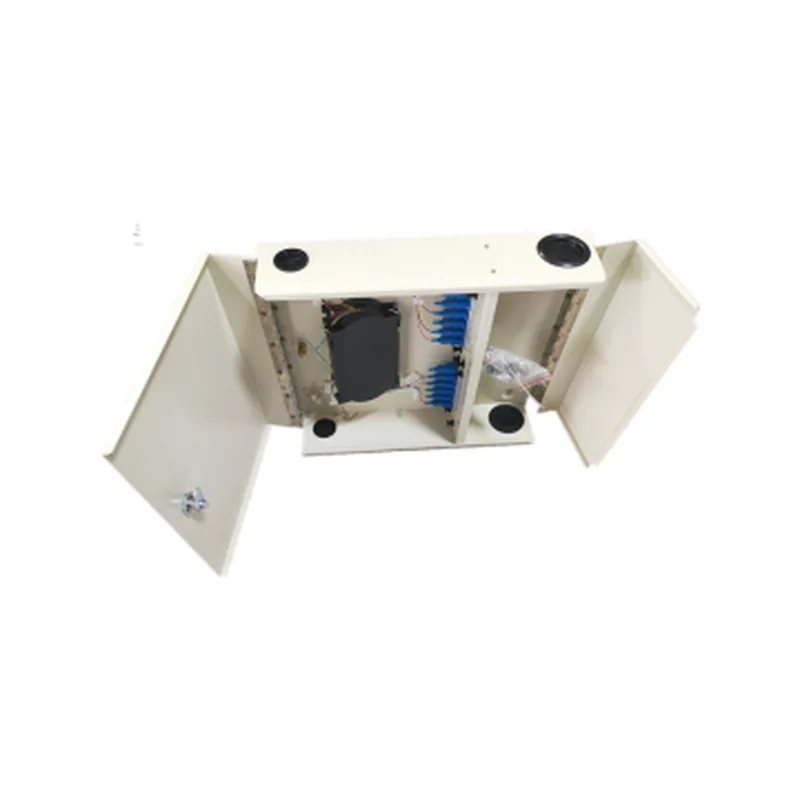
Choose a rack-mount ODF when...
- The fibre lands in a 19-inch rack with the OLT, core switch or router, so patch cords stay short and inside the rack.
- You'll be working on live fibre. On the ARC-ODF-RM-2U, one tray slides out for splicing or inspection while the other 12 positions stay untouched and in service.
- The room is controlled: a comms room, data centre or ISP point of presence.
Choose a wall-mount ODF when...
- The cable enters a building, riser cupboard or plant room with no rack.
- You need to separate the incoming feeder from outgoing drops at one wall point. The ARC-ODF-WM-24's central adapter board does exactly that.
- The space is shared or public: every ARC-ODF-WM-24 cabinet has a lock.
- You want LC density on the wall: up to 48 LC-duplex instead of 24 SC.
Neither is an IP-rated outdoor enclosure. The ARC-ODF-WM-24 suits indoor and sheltered outdoor positions, but it is not IP-rated. For exposed outdoor plant, look at the IP-68 ARC-FDT-24-SCA distribution terminal or the IP68 ARC-DJC-16 dome splice closure; our guide to passive optical networks explains where those fit.
Fibre termination inside an ODF: splice trays, pigtails and adapters
Most ODF terminations follow the same path:
- The incoming cable enters from the top or bottom and is clamped and stripped back.
- Each fibre is fusion-spliced to a pigtail (a short, factory-terminated fibre with a connector on one end), and the joint sits in a fibre splice tray.
- The pigtail connector plugs into the back of an adapter.
- A patch cord plugs into the front and runs to the equipment.
Because the field cable is spliced rather than connectorised on site, the adapter face becomes the clean, testable demarcation point. Re-patching later never disturbs a splice.
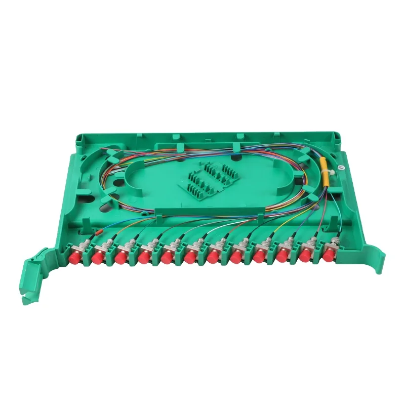
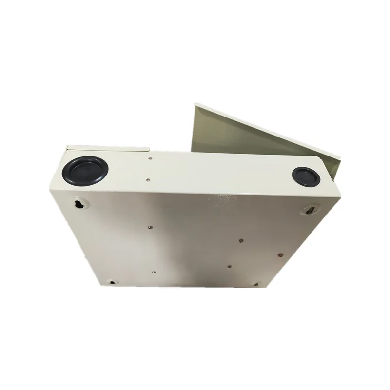
What to order with the frame. Both ARC DATA ODFs ship with installation accessories, and the adapter type (SC, LC or FC) is specified when you order. You'll also need:
- pigtails for splicing, in the same connector and polish as the adapters
- adapters to your standard
- patch cords to the active equipment, such as the ARC-OLT-8X
In Australia, fixed fibre cabling on customer premises must be installed by an ACMA-registered cabler with the appropriate endorsement.
SC vs LC connectors: which should the ODF use?
Both are common on fibre patch panels. The difference is mostly size:
| SC | LC | |
|---|---|---|
| Ferrule | 2.5 mm | 1.25 mm |
| Latch | Push-pull, square body | Latching clip, small form factor |
| Density | Lower; easy to handle with gloves or in a cramped cabinet | About twice the ports in the same panel space |
| Where you see it | PON and FTTH plant; ODFs and terminals | Switch and router SFP and SFP+ optics; high-density patching |
| On the ARC-ODF-WM-24 | Up to 24 SC | Up to 48 LC-duplex |
Both ARC DATA ODFs also take FC adapters (screw-on coupling), specified at order.
Pick the connector your equipment and the rest of the plant already use, and keep it consistent. Most switch and router optics use LC, so a short LC-to-SC patch cord is normal between a switch and an SC panel. For choosing the optics themselves, see our SFP and QSFP optics guide.
APC vs UPC: green or blue connectors?
The polish of the connector end face matters as much as its shape:
| UPC (ultra physical contact) | APC (angled physical contact) | |
|---|---|---|
| End face | Flat, domed polish | Polished at an 8° angle |
| Usual colour | Blue (single-mode) | Green |
| Back-reflection | Higher | Lower: the angle sends reflected light out of the core |
| ARC-ODF-RM-2U return loss | 50 dB or better | 60 dB or better |
| Common use | Data-centre and enterprise patching | FTTH and PON builds |
Colours follow the common industry convention; always check the connector itself. Return loss figures are from the ARC-ODF-RM-2U datasheet (PC: 45 dB or better).
Never mate APC with UPC. The angled and flat end faces don't meet properly, which adds loss and can damage both end faces. Match the pigtails, adapters and patch cords on each port, and label the panel. In a PON, also check what the ONUs and terminals use: the ARC-FDT-24-SCA ships with SC adapters in APC or UPC.
Single-mode vs multimode fibre at the ODF
The ODF itself is just a frame. What matters is that the pigtails and patch cords match the cable you're terminating:
| Single-mode (OS2) | Multimode (OM3, OM4) | |
|---|---|---|
| Core / cladding | 9 / 125 µm | 50 / 125 µm |
| Usual jacket colour | Yellow | Aqua (OM3 and OM4) |
| Distance | Kilometres: campus, estate, ISP and PON links | Short links inside a building or data centre |
| PON and FTTH | Yes: PON runs on single-mode fibre | No |
Jacket colours follow the common convention; confirm from the cable print. Single-mode and multimode must never be mixed on one link.
For a PON head end with the ARC-OLT-8X, the whole optical distribution network (feeder, splitters, terminals and drops) is single-mode, so the ODF is fitted with single-mode pigtails and adapters.
Where the ODF sits in a PON or FTTH head end
In a passive optical network, the ODF sits between the OLT and the outside plant:
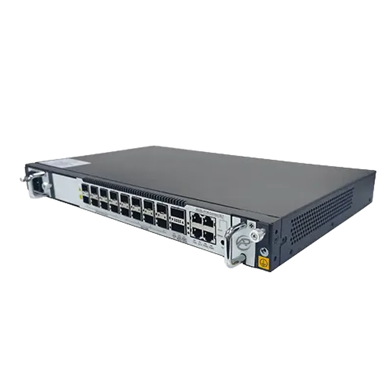
- OLT. The ARC-OLT-8X is a 1U, 19-inch OLT with eight XG(S)-PON and GPON combo PON ports on SFP+ slots, plus 1 x GE RJ45, 4 x 25GE SFP28 and 2 x QSFP28 (40/50/100GE) uplinks. Patch cords run from its PON optics to the front of the ODF.
- ODF. The ARC-ODF-RM-2U in the same rack splices those positions onto the outgoing feeder cables.
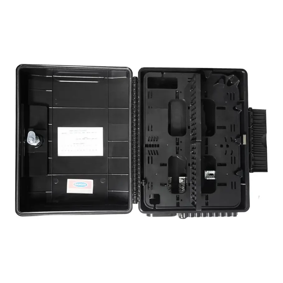
- Outside plant. Feeder fibre runs out through splice closures such as the ARC-DJC-16 to distribution terminals such as the ARC-FDT-24-SCA (24 waterproof SC ports, IP-68), then to an ONU at each premises.
Closures, terminals, splitters and ONUs are covered in our passive optical network guide.
How many cores does the ODF need?
Count every fibre that will land on the frame, then add spare positions for growth and repairs:
- one position per OLT PON port you'll light (the ARC-OLT-8X has eight)
- every core of each incoming and outgoing cable you terminate, not just the cores in use today
- any point-to-point links: switch uplinks, building-to-building links, CCTV backhaul
A 24-core frame such as the ARC-ODF-RM-2U or ARC-ODF-WM-24 covers a single OLT's eight PON ports with room for other links. For larger head ends, frames at 48, 72 and 96 cores are made in the same sliding-tray format, and a 12-core wall-mount version suits small building entries. Contact us for those.
Label as you go. Record which cable, core and far-end location each port serves, on the panel and in your as-built records. Months later, that saves a day of tracing.
Rack or wall ODF for which Australian site?
| Site | Usual choice | Why |
|---|---|---|
| ISP or WISP point of presence | Rack-mount | Sits beside the OLT and routers; trays serviced live |
| Data centre or comms room | Rack-mount | Short patch cords inside the rack; controlled room |
| Campus or hospital main comms room | Rack-mount at the core, wall-mount in buildings without racks | Head end in the rack, building entries on the wall |
| Hotel or apartment building (MDU) | Wall-mount at the entry and in risers | Lockable, separates feeder from drops per floor |
| Residential estate or holiday park | Rack-mount at the head end, wall-mount at building entries | Outdoor joints go in closures and terminals |
| Industrial site or plant room | Wall-mount in sheltered positions | Lockable, dust-proof steel cabinet; not for exposed outdoor spots |
ARC IP Networks suggestions based on the published specifications. We will check the design with you.
Contact us for project pricing
Send us your core count, connector standard and site layout. We will put together an ODF and patching bill of materials, from the frame and adapters to pigtails and patch cords, with project pricing. Call 1300 100 440.
ARC DATA ODFs and head-end parts
Full specifications are on each product page. For an ODF and patching bill of materials, call 1300 100 440.
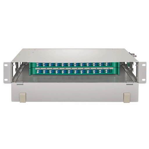
2U 19-inch ODF, 24 cores on two sliding trays of 12 SC, SC/LC/FC adapters, IL 0.3 dB or less. Contact us for availability and project pricing.
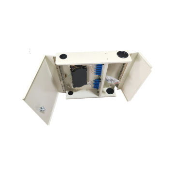
Lockable two-door wall-mount ODF for 24 SC, 24 FC or 48 LC-duplex, with splice tray. Contact us for availability and project pricing.
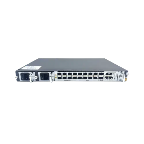
1U OLT, 8 XG(S)-PON / GPON combo ports, 25GE and 100GE uplinks. Contact us for availability and project pricing.
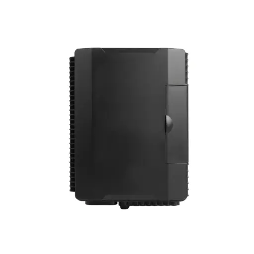
24 waterproof SC ports, 120 splices, up to three 1 x 8 PLC splitters, IP-68. Contact us for availability and project pricing.
Common questions
Straight answers from the ARC IP Networks team. Last reviewed November 2026.
An ODF (optical distribution frame) is the panel or cabinet where incoming fibre cables are terminated on adapter ports, spliced to pigtails, patched to the equipment they serve and stored within bend-radius limits.
ODF stands for optical distribution frame. It is the organised meeting point between incoming fibre cables and the equipment or drops they serve.
An ODF does the patching job of a fibre patch panel and also houses the splices and stores slack. The ARC DATA ARC-ODF-RM-2U combines adapters, splice trays and slack management for 24 cores in 2U.
Use a rack-mount ODF such as the ARC-ODF-RM-2U where the fibre lands in a 19-inch rack beside the OLT or core switch. Use a wall-mount ODF such as the ARC-ODF-WM-24 at a building entry, riser or plant room with no rack. Neither is an IP-rated outdoor enclosure.
A fibre termination box is a wall box where a cable is terminated and spliced, usually at a building entry. The ARC-ODF-WM-24 is a wall-mount fibre termination box and ODF in one, for up to 24 SC, 24 FC or 48 LC-duplex.
A splice tray holds and protects the fusion joints between the incoming cable and the pigtails, with the slack coiled inside bend-radius limits. Both ARC DATA ODFs have integrated splice trays.
SC uses a 2.5 mm ferrule in a square push-pull body. LC uses a 1.25 mm ferrule in a smaller latching body, so about twice as many fit in the same panel space. The ARC-ODF-WM-24 takes up to 24 SC or 48 LC-duplex.
UPC connectors have a flat polished end face and are usually blue on single-mode. APC connectors are polished at an 8 degree angle, are usually green and reflect less light back down the fibre. Never mate APC with UPC.
Single-mode. PON and FTTH run on single-mode fibre, so the ODF at the head end uses single-mode pigtails and adapters. Multimode (OM3, OM4) is for short links inside a building or data centre.
ARC IP Networks supplies the ARC DATA ARC-ODF-RM-2U rack-mount and ARC-ODF-WM-24 wall-mount ODFs, delivered Australia-wide. Call 1300 100 440 for availability and project pricing.
Related networking guides
- What Is a Passive Optical Network (PON)? A Guide for Australian Fibre Projects
- MikroTik SFP and QSFP Optics Guide: Which Fibre Module for Your Switch or Router
- Cisco SFP and Transceiver Guide: SFP, SFP+, QSFP and Stack Cables
- Netgear SFP+ Transceivers Explained: AGM, AXM and DAC Guide
- MikroTik Cloud Core Router (CCR) Guide for Australian ISPs and WISPs
- How to Run PoE Beyond 100 m in Australia: UniFi Long-Range Options